

Description
- GPS/GNSS disciplined 10 MHz
- OCXO or Rubidium timebase (opt.)
- Time tag events to UTC or GPS
- Frequency counter with 12 digit/s
- Source – Sine, square, triangle, IRIG-B
- Built-in distribution amplifiers
- Ethernet and RS-232 interfaces
FS740 GPS Time & Frequency System
The FS740 GPS/GNSS Disciplined Oscillator (GPSDO) provides a 10 MHz frequency reference which is disciplined by GPS with a long-term stability of better than 1 × 10-13. The instrument can also time tag external events with respect to UTC or GPS and measure the frequency of user inputs. The instrument has DDS synthesized frequency outputs, adjustable rate (and width) pulse outputs, and an AUX output for arbitrary waveforms including an IRIG-B timecode output.
The standard timebase provides 1 × 10⁻⁹ short-term frequency stability and phase noise of less than -105 dBc/Hz (10 Hz offset). An optional OCXO (ovenized crystal oscillator) timebase provides 1 × 10-11 short-term frequency stability and phase noise of less than -130 dBc/Hz (10 Hz offset). An optional rubidium timebase provides 1 × 10-12 short-term frequency stability, phase noise of less than -130 dBc/Hz (10 Hz offset), and a long-term holdover (lost GPS signal) of better than 1 μs/day.
Both optional timebases (OCXO or rubidium) provide a dramatic improvement in the holdover characteristics, a 30 dB reduction in the phase noise, and a tenfold reduction in the TDEV (rms timing deviation). There are some users who would not need this performance improvement. For example, users who only need time tags with 1 μs accuracy or frequency measurements with 1 × 10⁻⁸accuracy could use the standard timebase.
GPS Receiver
The FS740 provides bias for a remote active GPS antenna. The unit’s GPS receiver tracks up to 12 satellites, will automatically survey and fix its position, then use all received signals to optimize its timing solution. The FS740 time-tags the 1 pps output from the receiver, corrects the result for the receiver’s sawtooth error, then phase locks the timebase to the GPS 1 pps with an adjustable time constant between 1 minute and 10 hours. The TDEV between two instruments is a few nanoseconds.
If the GPS signal is lost, the timebase is left at the last locked frequency value. The timebase will age or drift in frequency by up to ±2 ppm (for the standard timebase), ±0.05 ppm/year and ±0.002 ppm (0 to 45⁰C) for the OCXO, and ±0.001 ppm/year and ±0.0001 ppm (0 to 45⁰C) for the rubidium timebase.
GNSS Antennas
You may choose to purchase a GPS antenna from SRS, or a third party, or use an existing GPS antenna at your facility. SRS timing receivers require a net gain (after cable losses) of +20 dBi to +32 dBi, which is a very common level from a variety of available active antennas and typical cable lengths. The antenna input to SRS timing receivers have a female BNC connector, provide +5 V bias, and have a 50 Ω input impedance.
SRS offers two antenna solutions, both of which have LNAs. All systems components have a 50 Ω characteristic impedance. For antenna details click here.
Graphical User Interface
A graphical user interface allows the user to configure the instrument and see the results of time and frequency measurements. The instrument can be configured in one of three modes: There are two user inputs (one on the front, one on the rear panel) for frequency and time tag events. The inputs have adjustable thresholds and slopes. Frequencies are measured with a precision of 1 × 10-11 in 1 s, 1 × 10-12 in 10 s, and 1 × 10-13 in 100 s. Time tags are reported with 1 ps resolution which is comparable to the short-term stability of the OCXO and rubidium timebases. Time tags will have an error of about 10 ns rms with respect to UTC or GPS time.
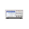
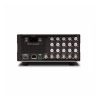
Front and Rear Panels
The FS740 has a rear-panel low phase noise (-130 dBc/Hz at 10 Hz offset) 10 MHz sine output with an amplitude of 1 Vrms. Up to 15 additional copies of the 10 MHz output are available via optional rear-panel outputs.
The FS740 has front and rear-panel SINE outputs which provide sine outputs from 1 μHz to 30.1 MHz with 1 μHz resolution, or a fixed 100 MHz, with adjustable amplitude from 100 mV to 1.2 V rms. Up to 15 additional copies of the SINE outputs are available via optional rear-panel outputs.
The FS740 has front-panel and rear-panel PULSE outputs which can provide low jitter (<50 ps,rms) pulses from 1 μHz to 30.1 MHz. The PULSE outputs have adjustable phase with respect to UTC and the pulse width can be set as narrow as 5 ns, or as wide as the entire pulse period minus 5 ns, with 10 ps resolution. Up to 15 additional copies of the PULSE outputs are available via optional rear-panel outputs.
The FS740 has front-panel and rear-panel AUX output which can generate standard or arbitrary waveforms (sine, ramp, triangle, etc.) The AUX output can also provide an IRIG-B timecode output. Both width coded pulses and amplitude modulated sine waves (with carrier frequencies from 100 Hz to 1 MHz) are available for the IRIG-B outputs. Up to 15 additional copies of the AUX output are available via optional rear-panel outputs.
A rear-panel alarm relay is set if power is lost or under user defined conditions including: timebase fault, loss of GPS reception, or any failure to maintain phase lock between the timebase and GPS. The relay has both normally open and closed outputs.
Distribution Amplifiers
Optional distribution amplifiers, each providing five additional rear-panel outputs for the 10 MHz, SINE, PULSE, AUX or IRIG-B outputs, can be installed. Up to three distribution amplifiers can be installed and configured from the front panel. Each output has its own driver which provides high isolation between outputs.